4 20ma circuit diagram
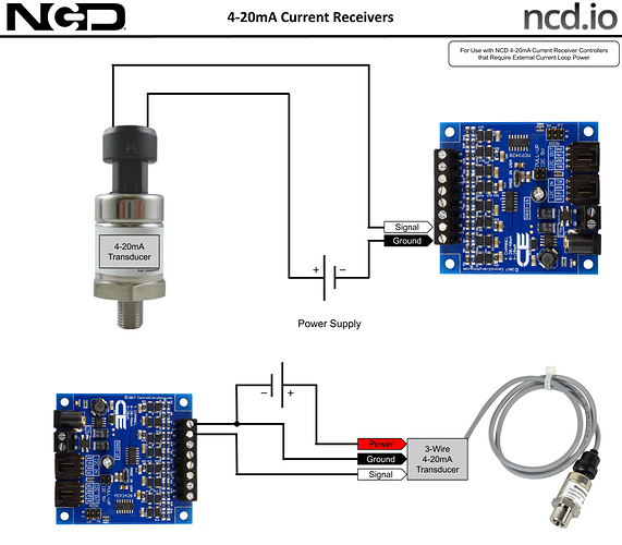
IoT Long Range Wireless 4-20mA Current Receiver - Products - NCD.io. 9 Pictures about IoT Long Range Wireless 4-20mA Current Receiver - Products - NCD.io : 4 20ma To 0 10v Converter Circuit Diagram, De Regreso a lo Básico: Los Fundamentos de los Lazos de Corriente de 4 and also IoT Long Range Wireless 4-20mA Current Receiver - Products - NCD.io.
IoT Long Range Wireless 4-20mA Current Receiver - Products - NCD.io
 community.ncd.io
20ma 1459 1276
What Are 2-wire And 4-wire Transmitter Output Loops? | RealPars
 realpars.com
wire loop transmitter diagram differential pressure analog current realpars wiring input plc volt illustrated supply power card series
A High Accuracy, Low-power, Easy To Use Novato MAXREFDES16 L
 www.maximintegrated.com
diagram 20ma hart loop temperature sensor powered block novato maxim power accuracy enlarge system
MAX14626 High-Voltage Reverse-Input-Capable 4–20mA Current Loop
 www.maximintegrated.com
loop current input 20ma circuit protection protector voltage diagram typical capable reverse analog sensor operating control
4-20 MA Source Circuit | Electronic Circuit Directory
 circuitelec.blogspot.com
current source constant op circuit amp transistor ma 20ma vref amplifier getting why voltage ie
2-wire 4-20mA Sensor Transmitters: Designing Input Isolated 2-Wire
 e2e.ti.com
20ma sensor wire input isolated transmitter ti transmitters e2e example designing figure
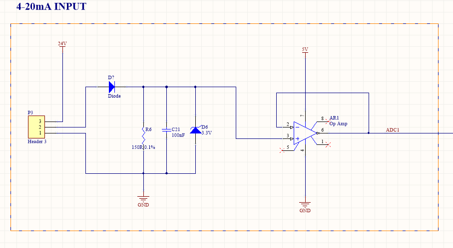
4 20ma To 0 10v Converter Circuit Diagram
 schematron.org
10v 20ma circuit converter diagram analog microcontroller wiring adc 3v inputs terminals outputs plug technical supply easy data
Complete Stand-Alone GPS Receiver Solution With MAX2742 - Application
 www.maximintegrated.com
gps receiver diagram block figure complete solution quartz crystals application implementation rf oscillators advanced lna alone stand
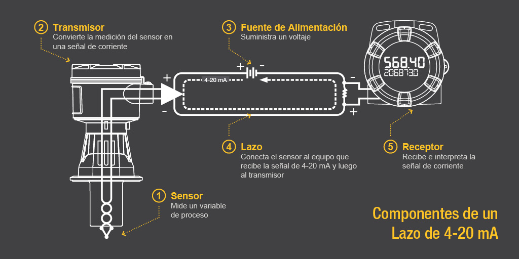
De Regreso A Lo Básico: Los Fundamentos De Los Lazos De Corriente De 4
 www.predig.com
10v 20ma circuit converter diagram analog microcontroller wiring adc 3v inputs terminals outputs plug technical supply easy data. Gps receiver diagram block figure complete solution quartz crystals application implementation rf oscillators advanced lna alone stand. What are 2-wire and 4-wire transmitter output loops?